BIOS (Basic Input Output System)

zjhl2lgef9cyrql0jfa7kzbw2vucrb5knhfe1td9oxde9g5shnn1i-bv9ettdv9dsbugw0py
BIOS (Basic Input Output System)

  • BIOS is the program a computer’s microprocessor uses to get the computer system started after you turn it on.

  • It also manages data flow between the computer’s operating system and attached devices such as the hard disk, graphic card, keyboard, mouse and printer.

  • BIOS is a chip located on all motherboard that contain instruction of how your system should boot and how it operate.

  • The BIOS include instruction on how to load basic computer hardware & include a test referred as a POST that verifies the computer needs requirement to boot up properly.

  • If the computer does not pass the POST, you will receive a combination of beep indication that indicates malfunctioning within the computer.


POST:

  • POST is a test the computer must complete to verify all hardware is working properly before starting the remainder of the boot process.

  • If the computer passes the POST the computer will often return a single beep and if unsuccessful will create a beep code that indicates the error.


What do you meant by the term ROM BIOS (Read Only Memory BIOS)?

  • Read only means that the Program and data can only be read from it. Therefore Program and data cannot be written to it.

  • Most Computer contain small amount of ROM to stores programs that enable the computer to boots.

  • It is a non- volatile memory and hence it is referred as a permanent data storage area.

  • The BIOS in a PC is stored on a ROM chip located on the motherboard.

  • Early PCs used a ROM BIOS, but PCs today use a flash memory BIOS because it can be updated in place.

  • In order to update a ROM BIOS, the computer case had to be opened, and the ROM chip had to be located and replaced.


How do I get to BIOS in Windows 7?

  • Turn off the computer and wait five seconds.

  • Now turn on the computer and immediately press the F10 key or F1 key  three to four times after you see company logo on display until a BIOS Setup screen opens.
  • In the BIOS Setup utility, do one of the following: On the Main tab, find the BIOS version.

Note: – Different Company models Had Different Keys to go in Bios Screen Option.


What do mean by Dual BIOS?

  • Dual BIOS mean there are two ROM Bios IC Chip present on the Motherboard.

  • A dual BIOS is a computer motherboard that contains a main BIOS and a backup BIOS.

  • This type of setup can help a motherboard recover from any problems encountered during a BIOS update.

  • It also helps protect the BIOS from any potential virus, or any other data corruption that might occur.

View BIOS information at POST

hf

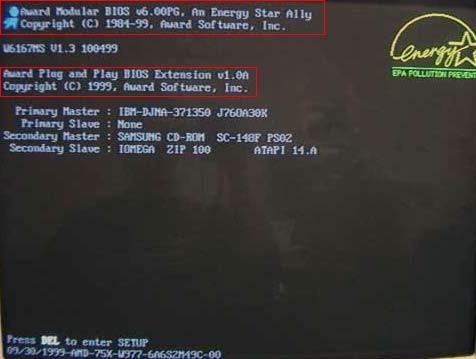
  • The first way is by restarting your computer.
  • When the initial load (also called POST) screen is displayed, the BIOS Type and version is also displayed.
    Tip: If the load screen is displayed for only a few seconds, you can try pressing the Pause/Break key on your keyboard to pause the loading process.
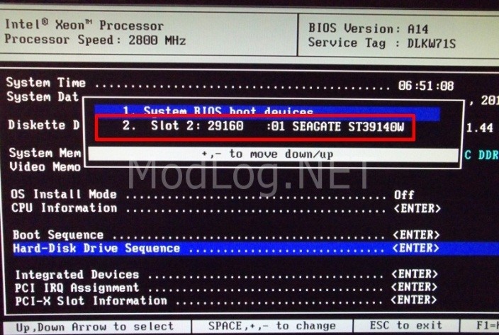
  • The BIOS information is typically found at or near the top of the POST screen.
  • Also, you will see information on what hard drive(s) and CD/DVD drives are installed in your computer.


Through Windows System Information

fhg

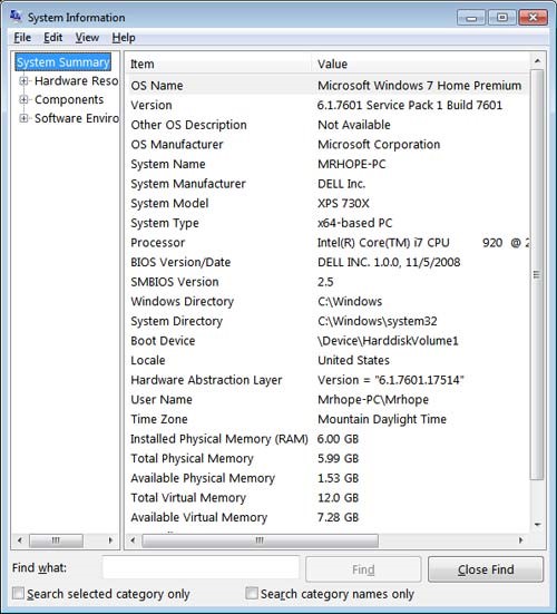
  • The BIOS information is also shown through the Windows System Information.
  • To open this tool click start, Programs, Accessories, System Tools, and then System Information.
  • If you’re running Windows Vista or Windows 7, type System Information in the Start search box.
  • In the System Information window, displaying information about your computer, including the type of BIOS you have and the version, under the System Summary section.
  • As can be seen in the picture below, this computer has a DELL BIOS version 1.0.0 with a Date of 11/5/2008.


Windows Registry


iuy

  • You can also find BIOS information in the Windows System Registry.

  • While in the registry realize that improperly changing a setting can affect how Windows operates.

  • To access the System Registry, click start and in the Run or Search box type reg edit in the text field and press enter. In the Windows Registry navigate to the below Registry directory.
    Hkey_local_machine\hardware\description\system

  • Find the sub keys System Bios Date and System Bios Version to see the BIOS and version for your motherboard. As can be seen in the picture below, the BIOS date and version are shown in these two keys.


Types of BIOS: –

  • Single Page BIOS.
  • Multi Page BIOS/ Five Page BIOS.
  • Explorer BIOS.
  • Phoenix BIOS.
  • UEFI BIOS (Unified Extensible Firmware Interface).


  1. Single Page BIOS: –

  • In Single Page Mode BIOS all the Option are in one single Page.

  • It can be seen in early 90’s computer.

erw


  1. Multi / Five Page BIOS: –

  • Multi page or Five page Mode BIOS has 5 different option namely Main, Advanced, Security, Boot, Exit.

rtre


  1. Explorer BIOS:-

  • This BIOS is Windows Explorer Lookalike.

  • It is the only BIOS where we can use Mouse.

65y


  1. Phoenix BIOS : –

  • Phoenix BIOS is the commonly see BIOS in nowadays new and old Computer.


nm


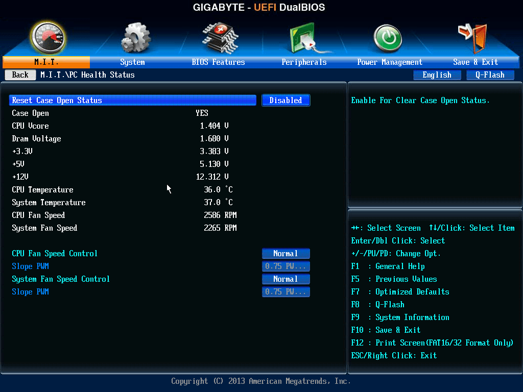
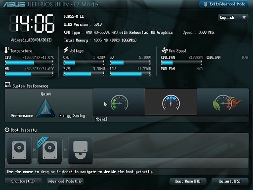
  1. UEFI BIOS (Unified Extensible Firmware Interface): –

  • UEFI Bios is the latest Bios used in new computer.
  • UEFI Bios is mostly used in Windows 7, Windows 8, Windows 8.1 and Windows 10.

  • This bios help the computer to boot up faster than any other bios.

sdfs


gfhf


Hard disk & its types

Hard disk


  • Hard disk is a rigid non-removable magnetic disk with a large data storage capacity.
  • The hard drive is the computer’s main storage media device that permanently stores all data on the computer.
  • The hard drive was first introduced on September 13, 1956 and consists of one or more hard drive platters inside of air sealed casing.
  • Most computer hard drives are in an internal drive bay at the front of the computer and connect to the motherboard using either ata, scsi, or a sata cable and power cable.


Types of Hard disk

  1. IDE (Integrated Device Electronic) or ATA (advance technology attachment).
  2. SATA (serial advanced technology attachment).
  3. SCSI (small computer system interface).
  4. External Hard Drive.
  1. IDE (Integrated Device Electronic) or ATA (Advance Technology Attachment) :
  • IDE is a standard electronic interface used between a computer motherboard’s data paths or bus and the computer’s disk storage devices.
  • The IDE interface is based on the IBM PC Industry Standard Architecture (ISA) 16-bit bus standard, but it is also used in computers that use other bus standards.
  • Most computers which are sold recently, uses an enhanced version of IDE called Enhanced Integrated Drive Electronics (EIDE).
  • We can connect maximum two hard disk to a single controller, or one hard disk and one DVD Drive to a single controller.
  • Speed of IDE hard disk is 100 MB per second.
  • We have to perform Jumper Setting on Hard disk or IDE Optical Drive for connecting two or more Hard disk or Optical Drive.


Setting as a Master:

  • Use this setting if you are installing an additional hard disk drive to a single IDE cable with a hard disk drive Set as Slave, jumper one hard disk drive to Set as Master, and the other to set as Slave. 
  • Use this setting if you are installing an additional hard disk drive to a single IDE cable and the Cable Select setting is not recognized.

       Set as Slave:

  • Use this setting if you are installing an additional hard disk drive to a single IDE cable with a hard disk drive Set as Master, jumper one hard disk drive to Set as Master, and the other to set as Slave. 
  • Use this setting if you are installing an additional hard disk drive to a single IDE cable and the Cable Select setting is not recognized.

       Cable Select:

  • This setting is the default setting for pata / ide hard disk drives. 
  • With the Cable Select jumper setting, the BIOS determines whether a hard disk drive is Set as Master or Set as Slave by its position on the IDE cable. 
  • If the hard disk drive jumper is set to Cable Select and is connected to the black connector on the end of the IDE cable, it is recognized as Set as Master for that pata controller. 
  • If the hard disk drive jumper is set to Cable Select and is connected to the grey connector on the middle of the IDE cable, it is recognized as Set as Slave for that pata controller.

Note: When using Cable Select, your system must meet the following conditions:

  • Your systems host controller must support Cable Select.
  • Your hard drives must support Cable Select.
  • Your cable must support Cable Select.


  1. SATA (Serial Advance Technology Attachment): 

ewfg

  • Serial Advanced Technology Attachment, often abbreviated SATA , is a serial link – a single cable with a minimum of four wires creates a point-to-point connection between devices.
  • One of the main advantages of Serial ATA is that the thinner serial cables facilitate more efficient airflow inside a form factor and also allow for smaller chassis designs.
  • As an evolution of the older Parallel ATA physical storage interface, SATA host-adapters and devices communicate via a high-speed serial cable.
  • Several advantages over the older interface: reduced cable size and cost, native hot swapping, faster data transfer through higher signaling rates.
  • We can connect n number of sata hard disk or Optical drive depends upon the number of sata port available on the motherboard.
  • Sata data connector has 7 pins whereas Sata power connector has 15 pins.
 Standard  Data connector Pins Connections
Pins Similar Function
1 1st Ground
2 2nd A+ (transmit)
3 2nd A- (transmit)
4 1st Ground
5 2nd B – (receive)
6 2nd B + (receive)
7 1st Ground
—- —– Coding Notch


             Standard Power Connector Pins Connections
Pins Similar Function
—– Coding Notch
1 3rd      3.3 Volts Power
2 3rd
3 2nd Enter/exit Power Disable (PWDIS) mode
4 1st  

Ground

5 2nd
6 2nd
7 2nd  

5 Volts Power

8 3rd
9 3rd
10 2nd      Ground
11 3rd Staggered spin up/activity
12 1st      Ground
13 2nd  

12 Volts Power

14 3rd
15 3rd


  • Speed of Sata drive according to their version:
  1. Sata 3.2 16 Gbit/s
  2. Sata 3.0 6 Gbit/s
  3. Sata 2.0 3 gbit/s
  4. Sata 1.0 5 Gbit/s

3. SCSI (Small Computer System Interface)


rger

  • Small Computer System Interface is a set of standards for physically connecting and transferring data between computers and peripheral devices.
  • SCSI is capable of supporting eight devices, or sixteen devices with Wide SCSI.
  • SCSI is a standard for parallel interfaces that transfers information at a rate of eight bits per second and faster, which is faster than the average parallel interface.
  • SCSI-2 and above supports up to seven peripheral devices, such as a hard drive, CD-ROM, and scanner, that can attach to a single SCSI port on a system’s bus.


  1. External Hard Disk. 


  • External HDD typically connect via USB; variants using USB 2.0 and Others interface generally have slower data transfer rates when compared to internally mounted hard drives connected through SATA.
  • Plug and play drive functionality offers system compatibility and features large storage options and portable design.
  • External HDDs are usually available as pre-assembled integrated products, but may be also assembled by combining an external enclosure (with USB or other interface) with a separately purchased HDD.
  • They are available in 2.5-inch and 3.5-inch sizes; 2.5-inch variants are typically called portable external drives, while 3.5-inch variants are referred to as desktop external drives.